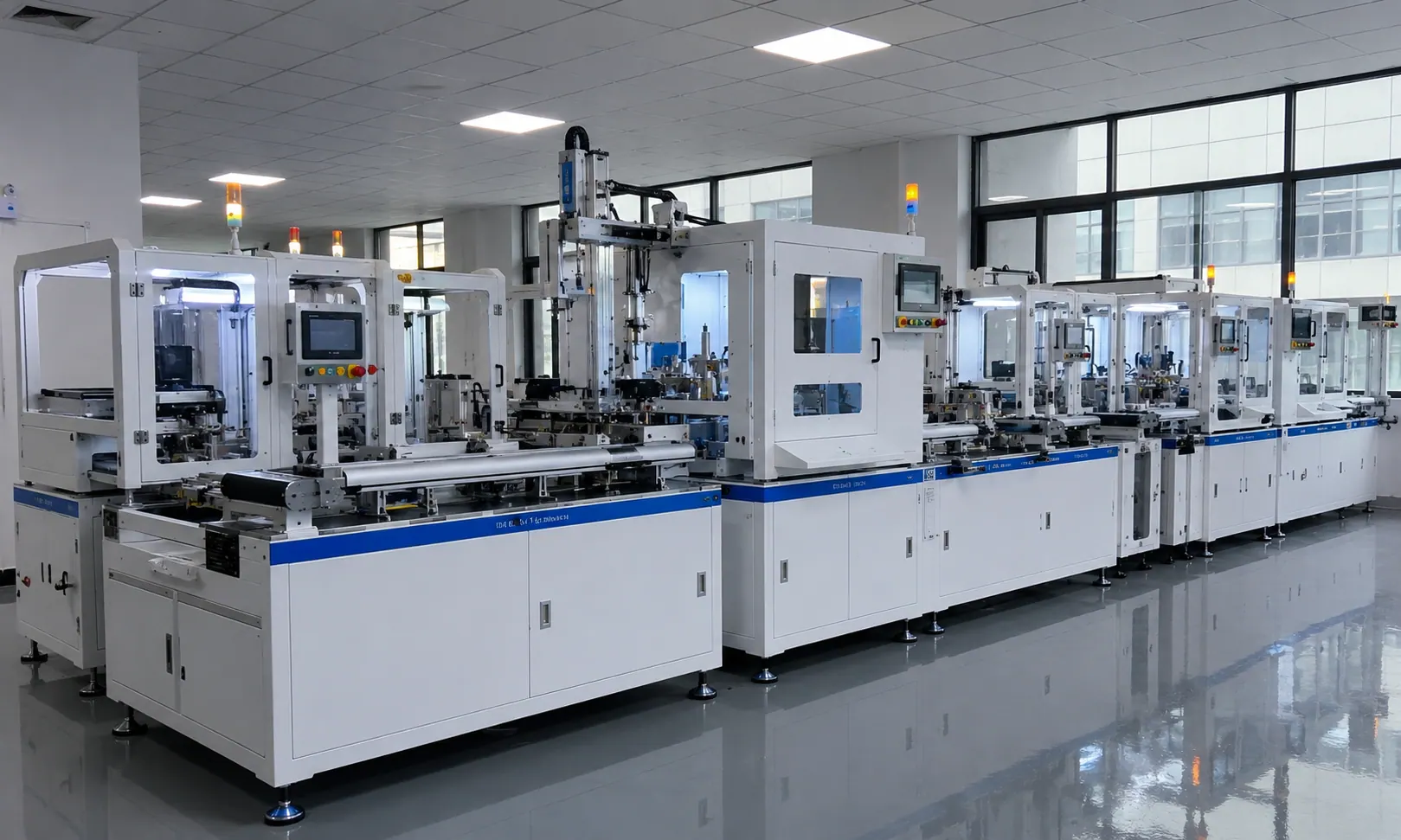
PV JUNCTION BOX AUTOMATION

PV Junction Box
Assembly Line

Industrial turnkey automation for housing, module diode loading, pressure block process, cable preparation, testing and final unloading.

Built for module junction box production teams that need a clear front-end / back-end layout, synchronized cable process control and stable high-volume output.

1000-1100 set / hour target output
L10000 overall line length
4 operators configured
15KW installed line power
SolarOne PV Junction Box Assembly Line
COMPONENTS & MATERIALS

Components Handled Across Junction Box Assembly

Key product modules and process materials handled by the line, from housing and diode preparation to pressure block, cable, testing, labeling and separated unloading.

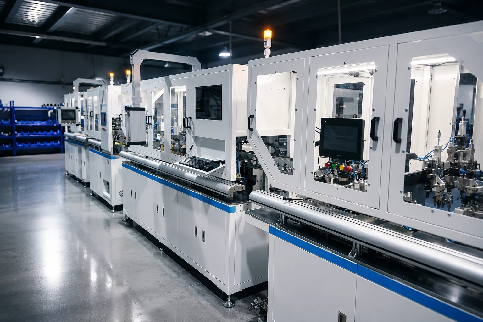
PV Junction Box automatic line production arrangement
System configuration

Front-end + back-end coordinated assembly architecture

The line combines front-end module and housing preparation with back-end cable process, press board loading, soldering, testing, laser labeling and controlled unloading for positive, negative and middle parts.
Key Components
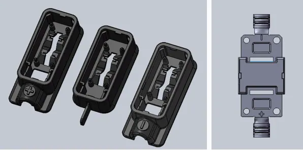
Three-Part Housing Module

Structured junction box shell set prepared for downstream automated assembly.

Module Diode

Front-end loading item coordinated with housing preparation and positioning.

Pressure Block / Press Board

Loaded and processed before the back-end soldering and verification sequence.

Cable and Terminal Process

Manual loading, stripping, wire feeding, riveting and soldering in linked stations.

Testing and Laser Labeling

Middle-part testing, final electrical checks and traceable marking before discharge.

Separated Unloading Paths

Positive, negative and middle-part outputs handled through dedicated discharge logic.

ENGINEERING DESIGN

Design Rationale and Deployment Context

Engineering decisions behind the front-end and back-end assembly architecture and the production environments where the complete line performs best.

Engineering Advantages

01
Front-End / Back-End Split

Separates housing and module preparation from cable-intensive downstream processes while keeping one coordinated line rhythm.

02
Multi-Lane Product Handling

Positive, negative and middle-part logic is organized so different outputs can be assembled and unloaded without a single bottleneck.

03
Integrated Cable Process

Back-end stations link cable loading, stripping, wire feeding, riveting and soldering into one traceable workflow.

04
Test and Marking Closure

Electrical testing and laser labeling close the quality loop before the final unload paths release finished parts.

05
Expandable Process Console

The line layout supports engineering review of module, arrangement, dimensions and process flow from one visual system.

Ideal Production Scenarios

A
Module Junction Box Assembly

High-volume production where housing, diode, pressure block and cable operations need one automated line.

B
Positive / Negative Output Lines

Factories that need controlled handling for positive, negative and middle-part product flows.

C
Cable Process Integration

Production sites consolidating cable preparation, riveting, soldering and test into one downstream section.

D
Traceability-Driven Manufacturing

Lines requiring final test, laser marking and separated unloading to support quality records.

E
Full-Line Automation Projects

End-to-end upgrades replacing isolated manual stations with a coordinated industrial assembly platform.

INTERACTIVE LINE EXPLORER

Explore Module, Layout, Flow and Parameters in One Industrial Console

Select a view to switch between the housing module, overall arrangement, front-end dimension, back-end dimension and process flow. The console keeps the interaction focused instead of auto-rotating through every state.

View 01

Three-Part Junction Box Housing Module

The housing module side organizes the three-part junction box shell set before the rest of the line engages the module diode, pressure block and cable process. This is the cleanest way to understand the physical product base the line is built around.

Three-part housing Module-ready geometry Front-end product reference
Housing preparationShell geometry is stabilized before entering the automated line sequence.
Product contextThis module view supports engineering discussion around housing fit, module placement and downstream pressure block logic.
Industrial continuityThe same product structure drives the front-end line architecture and the later unloading logic.
View 02

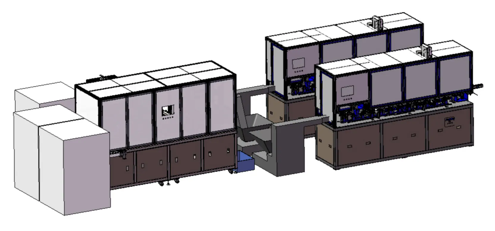
Arrangement of Automatic Assembly Line

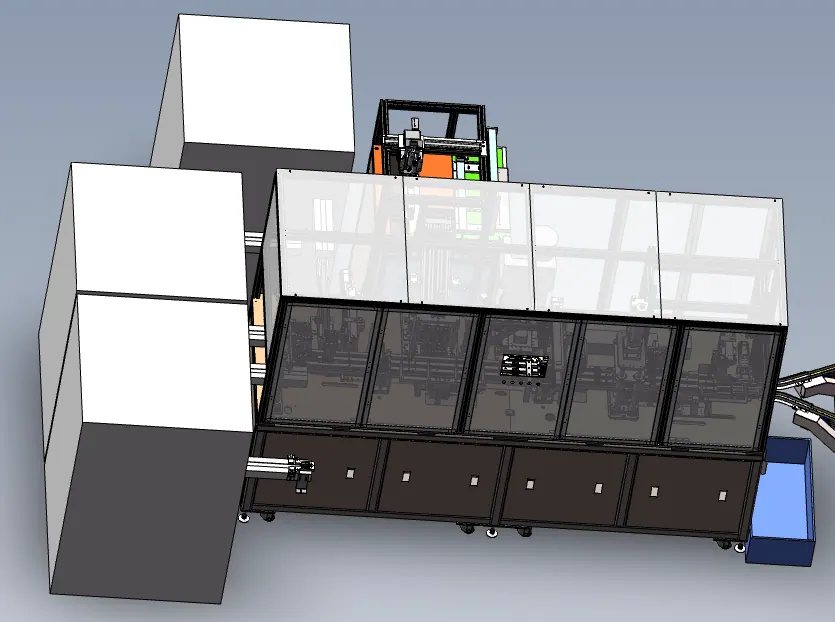
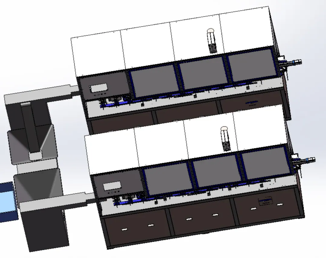
The overall arrangement shows how the line splits the workload across a front-end preparation unit, transfer bridge and dual downstream machine bodies. It reflects the same industrial footprint and massing language already used on the rest of the site.

Transfer bridge Dual backend tools Industrial footprint
Front-end cellHandles loading and early material organization before the main line sequence continues.
Bridge synchronizationTransfer hardware coordinates product movement between machine bodies without breaking takt continuity.
Backend splitTwo downstream bodies support different process groups while maintaining overall assembly rhythm.
View 03

Front-end

The front-end focuses on loading, housing movement and module diode preparation before material is handed into the later cable and unload logic. It reads as a dense, compact block because this part of the line is meant to stabilize incoming product conditions.

Loading sideTwo loading arrows indicate the incoming material face before housing movement begins.
Module diode loadingDedicated top-side operation integrated into the front-end body.
Unload separationPositive/negative part unloading and middle-part unloading are read as distinct downstream outputs.
View 04

Back-end

The back-end is where the cable-centric sequence becomes visible: manual loading support, press board loading, soldering, test, laser labeling and unloading. The composition is intentionally denser because the backend carries more process variation.

Manual loading interfaceOperator-accessible point for the backend cable process and fixture sequence.
Press board loadingIntegrated upper process branch feeding into the later solder and verification chain.
Unload consistencyBackend unload faces are aligned with the production exit rhythm and traceability flow.
View 05

Automatic Assembly Line Process Flow

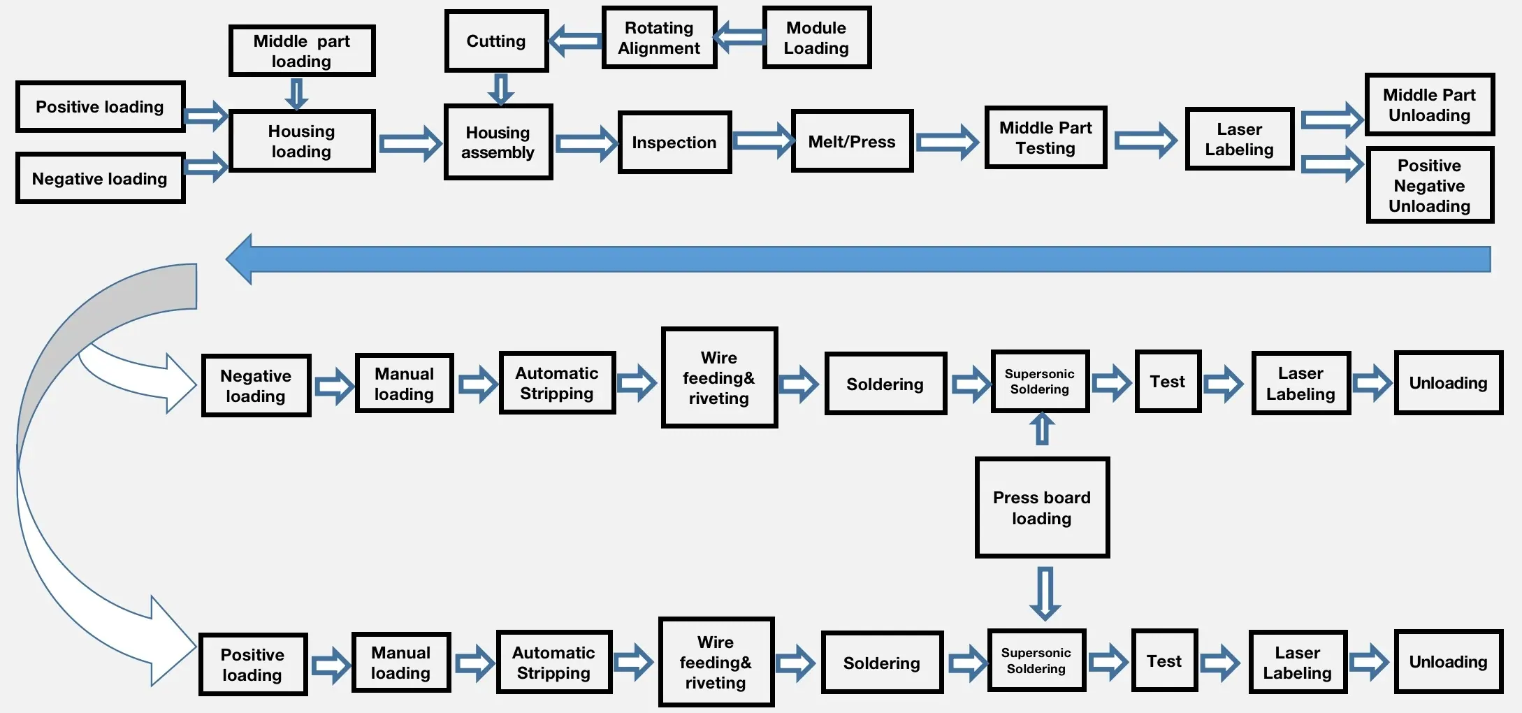
The line is not a single straight path. It is a coordinated group of housing, module and cable sub-flows that converge through inspection, pressing, soldering, testing and labeling before unloading. This process map image keeps that multi-lane logic clear at a glance.

Housing lane Cable lane Module lane
Housing pathPositive/negative loading, housing loading, housing assembly and middle-part verification.
Cable pathManual loading, stripping, wire feeding, riveting, soldering, test and labeling.
Converged outputInspection and downstream handling close the loop before final unloading.
LINE PARAMETERS

PV Junction Box Assembly Line Parameters

Dimensions L10000 * W4500 * H2000 mm
Takt Time 1000~1100 set / Hours
Voltages AC 220V ±10%
Powers 15KW
CDA Pressure 0.6 ~ 0.8Mpa
Weight 1500KG
CDA Consumption 80m³/h
Operator 4 operators
ENGINEERING REFERENCES

FAQ, Knowledge Centre and Case Studies

These links answer procurement and manufacturing questions around line sizing, utilities, inspection strategy and commissioning risk.

Frequently Asked Questions

01What is a PV junction box assembly line?

It is an integrated automation system that connects housing loading, cable preparation, assembly, inspection, testing and marking into one controlled production flow.

02Why is line balance more important than peak station speed?

A single fast station does not guarantee stable output. The real line performance depends on feeding stability, buffer logic, test yield and how smoothly each station hands products to the next step.

03What information is useful before discussing a line project?

Useful inputs include junction box drawings, sample parts, target output, quality requirements, current workshop layout and any preferred process standards.

04How should quality data be planned in a PV junction box line?

Quality data should connect key stations such as assembly checks, electrical testing, laser marking and NG handling so production teams can trace defects back to the process source.

05Why does sample testing matter before final line design?

Samples reveal small differences in housing fit, cable stiffness, terminal condition and part feeding behavior that are difficult to judge from drawings alone.

06What makes a line easier to maintain after installation?

Clear access around stations, modular tooling, readable HMI alarms and practical spare-part planning make daily maintenance and fault recovery much easier.

Linked References