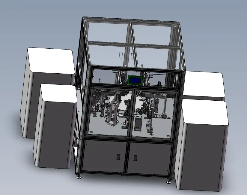
System configuration
Positive + Negative Assembly Set
The assembly system is configured as a matched positive and negative machine set. The product image shown represents the positive-side assembly unit.
Designed with an indexing assembly station and modular feeding system for efficient, reliable and continuous production.
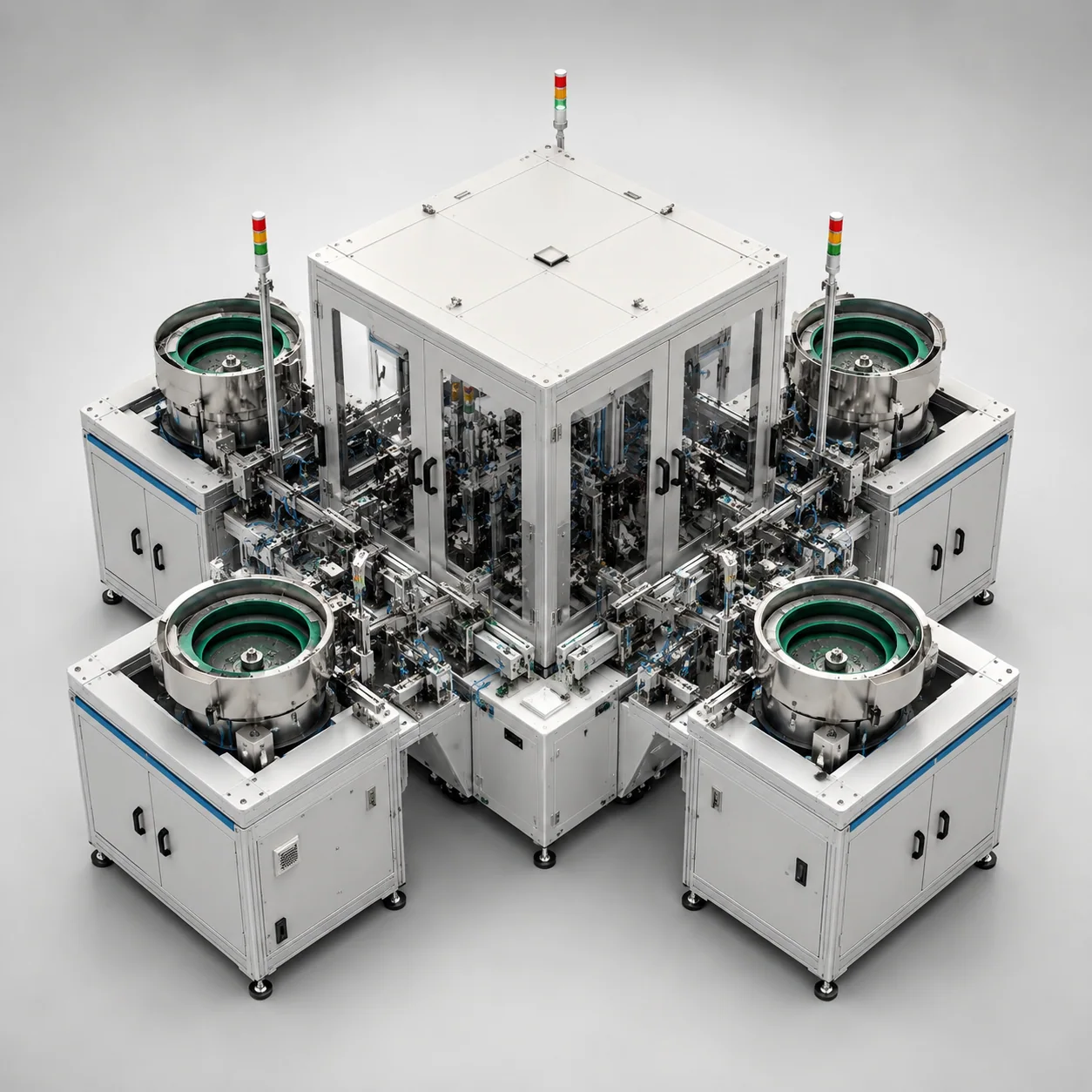
Key connector parts assembled by the system, from plastic housing and sealing components to contact parts and final threaded locking.
The assembly system is configured as a matched positive and negative machine set. The product image shown represents the positive-side assembly unit.
Main housing positioned as the carrier for all downstream assembly steps.
Locks the internal structure and supports stable connector build quality.
Sealing component installed with presence and seating verification.
Inserted connector element forming the electrical interface path.
Contact component loaded and aligned before final connector completion.
Threaded part tightened at the final station to complete assembly.
Engineering decisions behind the connector assembly architecture and the production environments where a two-unit set is most effective.
Organizes housing, ring, seal, plug, contact and nut operations into a single indexed assembly logic.
Uses dedicated positive and negative assembly machines to form a complete connector production set.
O-ring presence and seating checks help prevent missing, doubled or misaligned sealing defects.
Station-by-station positioning keeps small connector parts oriented through feeding, insertion and tightening.
OK and NG handling keeps assembly quality reviewable without slowing the main production rhythm.
Dedicated production of connector subassemblies before cable or junction box integration.
Factories requiring matched positive and negative connector output from one automation package.
Connector models where O-ring reliability and seating consistency are major quality gates.
Plants moving away from hand-loaded rings, plugs, contacts and nut tightening steps.
Works as an upstream connector preparation module for broader PV cable automation lines.
Move through the process flow to see how feeding, assembly, inspection and unloading are arranged around the indexing platform.
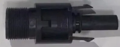
Connector bodies enter the indexing fixture and are accurately located as a repeatable assembly reference.
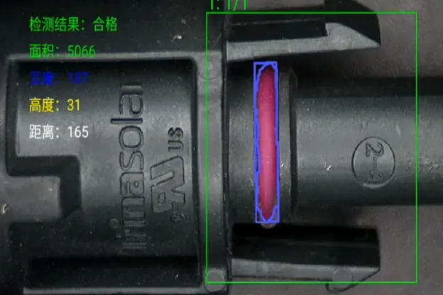
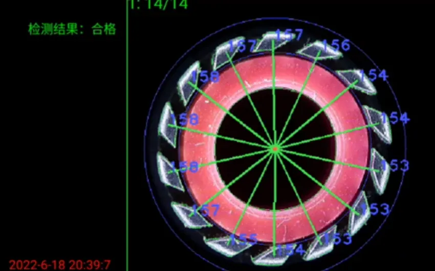
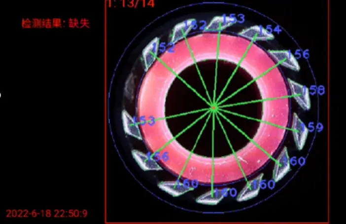
The process adds visual inspection for positive electrode O-rings and assembled basket-type plugs, helping detect missing installation, multiple rings, misalignment and improper seating.
The vision recipe can be switched by connector model to keep independent OK/NG limits for different product samples.
CCD captures the O-ring and seating zone image.
System extracts contour, center and area data.
Radius and offset values are compared with limits.
Qualified parts continue and NG parts are isolated.
 OK
Sample OK
OK
Sample OK
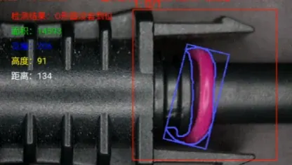
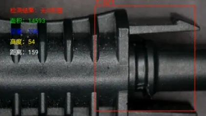
O-ring not installed correctly in the target zone.
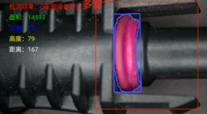 NG
NG Sample2
NG
NG Sample2
More than one O-ring detected at the same station.
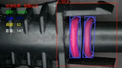 NG
NG Sample3
NG
NG Sample3
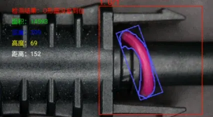
Center position exceeds configured tolerance range.
 NG
NG Sample4
NG
NG Sample4
Seating depth or contour fails the acceptance criteria.
The vision recipe can be switched by connector model to keep independent OK/NG limits for different product samples.
 OK
OK
 NG
NG
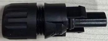
Reference positive and negative connector variants with clear model tags for fast engineering alignment.
 POSITIVE
MODEL MC4
POSITIVE
MODEL MC4
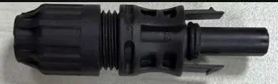 POSITIVE
MODEL QC4
POSITIVE
MODEL QC4
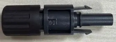 POSITIVE
MODEL TS4
POSITIVE
MODEL TS4
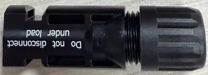 NEGATIVE
MODEL MC4
NEGATIVE
MODEL MC4
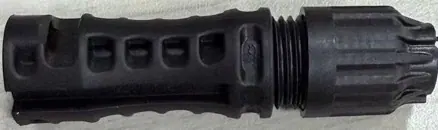 NEGATIVE
MODEL QC4
NEGATIVE
MODEL QC4
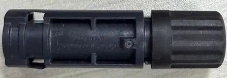 NEGATIVE
MODEL TS4
NEGATIVE
MODEL TS4
These references answer the practical engineering questions that come up during connector automation evaluation, from supported models to quality control and capacity stability.
A PV connector is the plug-and-socket component used to connect solar cables safely in a photovoltaic system. It must support reliable electrical contact, sealing and polarity control.
They are common PV connector families or model references used by different product platforms. Their geometry, seal stack and nut structure can differ, so automation support is confirmed with real samples.
Positive and negative connectors use different keyed shapes to prevent wrong mating in the field. Automation fixtures and feeding tracks usually need to respect that polarity difference.
These parts help protect sealing, mechanical locking and cable retention. Their position and assembly order directly affect connector reliability.
CCD inspection can check whether small parts such as O-rings are missing, doubled, tilted or seated incorrectly before the connector leaves the station.
Connector parts often look similar but behave differently in feeding and gripping. Sample validation helps confirm feeder design, fixture contact points and insertion motion.
Connector drawings, physical samples, part material, target output, acceptable inspection standards and expected model mix help define the automation concept.
Stable part feeding, controlled insertion force, clean fixture positioning and simple reject handling are usually more important than only increasing machine speed.