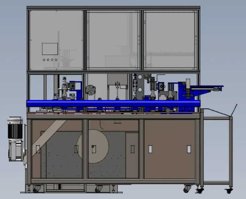
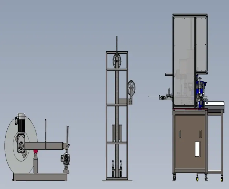
PV CABLE AUTOMATION

Cut, Strip, Rivet
& Tighten Machine

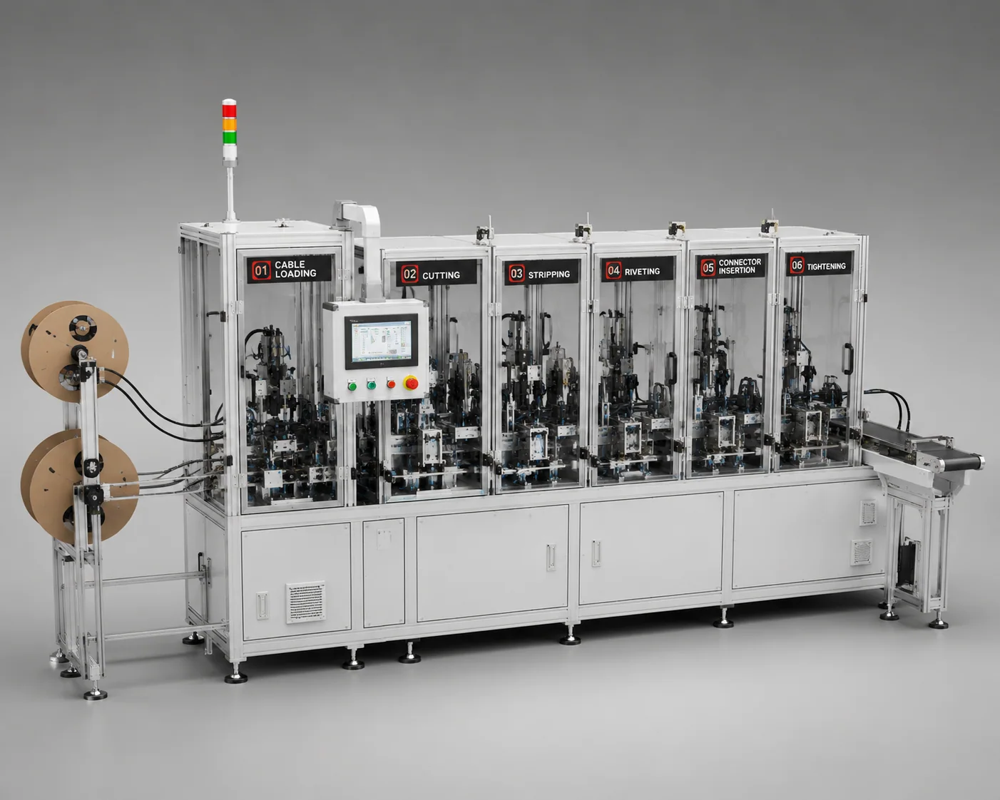
Integrated PV cable processing from loading and cutting to riveting, connecting and final tightening.

Designed as a positive and negative terminal assembly set for stable cable preparation, controlled riveting quality and continuous production flow.

1100-1200 pcs / hour target output
L3000 overall line length
1 operator configured
5KW installed line power
Cut strip rivet and tighten integrated machine
COMPONENTS & MATERIALS

Components Handled Across Cable Processing

Key cable, terminal and connector parts processed through loading, straightening, cutting, stripping, riveting, inspection, soldering, insertion and tightening.

System configuration

Positive + Negative Terminal Set

The integrated cutting, stripping, riveting and tightening machine consists of one positive terminal assembly unit and one negative terminal assembly unit, forming a complete set of two machines.
Key Components
PV Cable

Loaded, arranged, fed and straightened before cutting and stripping.

Stripped Cable End

Prepared conductor exposure for terminal riveting and soldering.

Terminal Assembly

Crimped, riveted and reinforced to form the electrical joint.

Inspection Area

Checks alignment, strand condition and riveting quality before assembly continues.

Connector Housing

Inserted after cable and terminal preparation are confirmed.

Finished Cable Set

Completed after connector tightening and final unloading.

ENGINEERING DESIGN

Design Rationale and Deployment Context

Engineering decisions behind the two-unit cable processing architecture and the production scenarios where it is most useful.

Engineering Advantages

01
Integrated Process Chain

Combines feeding, straightening, cutting, stripping, riveting, inspection, insertion and tightening in a coordinated flow.

02
Positive and Negative Units

Uses dedicated positive and negative terminal assembly units to complete a matched two-machine production set.

03
Vision-Guided Quality Gate

Inspection checks the riveting area before connector assembly, reducing hidden terminal defects.

04
Controlled Connector Tightening

Final tightening closes the assembly loop with repeatable engagement and feedback-ready process control.

05
Reduced Manual Handling

Automation removes repeated handoff between cable preparation, terminal processing and connector assembly steps.

Ideal Production Scenarios

A
PV Connector Cable Lines

High-volume production where cable end preparation and connector assembly need one controlled workflow.

B
Two-Polarity Manufacturing

Factories building complete positive and negative terminal sets for downstream junction box assembly.

C
Inspection-Critical Products

Applications where riveting alignment, strand condition and terminal integrity must be verified in process.

D
Manual-to-Auto Upgrades

Production cells replacing separate cutting, stripping, riveting and screwing workstations.

E
Line Integration Projects

Works as an upstream cable preparation module before final junction box or packing automation.

INTERACTIVE PROCESS FLOW

Ten-Station Cable Processing Flow

Move through the process flow to see how cable loading, arranging, inspection, cutting, stripping, riveting, soldering, connecting, tightening and unloading are organized.

Station 01

Cable Loading

PV cable is loaded into the machine and prepared for automatic feeding through the processing stations.

Engineering Focus
Consistent cable feed position before arranging, straightening and cutting.
Quality Control
Cable-present confirmation and stable feed control before downstream operations.
JOINING PROCESS COMPATIBILITY

Compatible Junction Box Joining Processes

This machine handles cable preparation processes such as cable feeding, cutting, stripping, terminal crimping and inspection. It can be integrated into complete PV junction box production lines using either riveting or resistance welding as the downstream joining process.

Riveting Process

01
Process Description

The prepared cable and terminal are mechanically joined to the junction box conductive component through a controlled riveting process. The production line may include crimp-height monitoring, pressure detection, visual inspection and pull-force verification.

A
Mechanical joining process

Crimping and riveting quality monitoring.

B
Compatible riveted designs

Suitable for compatible riveted junction box designs with stable and repeatable automated assembly.

Resistance Welding Process

01
Process Description

After cable cutting, stripping and preparation, the cable is positioned at a dedicated resistance-welding station and joined to the diode or conductive component. Welding current, pressure and process status can be monitored according to the product requirements.

A
Dedicated downstream welding station

Welding current and pressure monitoring.

B
Compatible resistance-welded designs

Process configuration depends on product materials and structure.

VISION INSPECTION

Riveting Quality Control

Inline camera inspection verifies riveting integrity and blocks NG parts before soldering and final tightening.

What This System Detects

  • Cable misalignment during riveting
  • Cable strand separation
  • Terminal damage after riveting
  • Insulation pinching or exposure

Configurable Inspection Items

Position X/Y Rivet profile Strand contour Insulation edge Terminal length Reject threshold

Recipe Flexibility

Recipe sets can be switched by cable model, terminal type and customer quality standard with separate OK/NG limits.

Inspection Workflow
Camera Capture

High-resolution image acquired in real time.

Vision Algorithm

Image processing and feature extraction.

Dimensional Measurement

Key dimensions and positions are measured.

Pass / Fail Decision

Result output, part sorting and data logging.

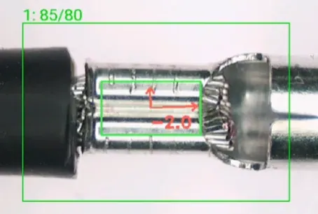
OK riveting sample captured by visual inspection system OK Sample OK
Reference OK sample: riveting area aligned, strand profile stable, terminal geometry accepted.
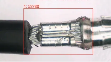
NG1 sample showing cable misalignment during riveting NG NG Sample1
Cable misalignment during riveting

Cable-to-terminal alignment deviation detected.

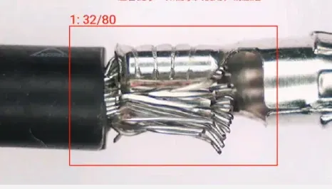
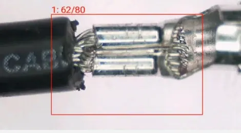
NG2 sample showing cable strand separation NG NG Sample2
Cable strand separation

Wire strands are exposed or separated beyond threshold.

NG3 sample showing terminal damage after riveting NG NG Sample3
Terminal damage after riveting

Terminal deformation or shape out of profile tolerance.

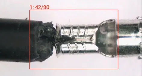
NG4 sample showing insulation pinching NG NG Sample4
Insulation pinching

Insulation pinched in the riveting zone.

MACHINE PARAMETERS

Cut-Strip-Rivet-Tighten Integrated Machine Parameters

Dimensions L3000 * W6000 * H2000mm
Takt Time 1100~1200pcs / Hours
Voltages AC 380V ± 10%
Powers 5KW
CDA Pressure 0.6 ~ 0.8Mpa
Weight 500KG
CDA Consumption 10m³/h
Operator 1 operator for 2 tools (positive & negative)
ENGINEERING REFERENCES

FAQ, Knowledge Centre and Case Studies

These references focus on cable process stability, terminal quality and the joining choices that affect throughput, rework and downstream assembly quality.

Frequently Asked Questions

01What does cut, strip, rivet and tighten mean?

It describes a cable-end preparation flow: cutting the cable, removing insulation, joining or fixing the terminal, and tightening the connector interface.

02Why is conductor strand condition important?

Loose, bent or missing strands can reduce electrical performance and make terminal joining unstable, so strand control is a key quality point in cable processing.

03What is the difference between riveting and crimping in cable processing?

Both are mechanical joining methods, but the tooling shape, force control and terminal design may differ. The right method depends on the cable and terminal structure.

04Why should samples be reviewed before automation design?

Cable stiffness, insulation thickness, terminal tolerance and connector fit all affect feeding, stripping, riveting and tightening stability.

05What defects should visual inspection look for?

Common checks include stripped length, terminal alignment, strand spread, missing material, deformation and connector seating condition.

06How can downstream connector assembly benefit from stable cable prep?

Consistent cable length, clean stripping and stable terminal geometry make later insertion, tightening and final inspection easier to control.

Linked References